EFZ-ESP32S3
The EFZ-ESP32S3 is the EmbeddedFun training board: an ESP32-S3 with every peripheral the course uses already on board.
Resources
Design files
| Revision | Schematic | Notes |
|---|---|---|
| V1 | EFZ-ESP32S3-V1-schematic.pdf (PDF, 9 sheets) | See the Rev 1 errata |
Zephyr board support
-
Build target:
efz_esp32s3/esp32s3/procpu(hardware model v2, vendorembeddedfun). -
Board files: devicetree, pinctrl, Kconfig and defconfig in
boards/embeddedfun/efz_esp32s3, with the board's Zephyr documentation page indoc/index.rst. -
Get it: create a workspace from the fork, as in Environment Setup & West:
west init -m https://github.com/huunghiaspkt/zephyr --mr main /your/workspace/path
Lessons
The whole Zephyr RTOS course runs on this board; every hands-on page has an EFZ-ESP32S3 tab. Good places to start:
| Lesson | On this board |
|---|---|
| Environment Setup & West | Install the tools, build, flash over USB-C and read the console |
| WS2812 RGB LED | The on-board RGB LED on GPIO21, added with an overlay |
| Sensors | The on-board SHT30 temperature and humidity sensor on I2C |
| WiFi · WiFi Shell | The ESP32-S3 radio: connect and scan |
| BLE Basics | Bluetooth LE from the ESP32-S3 |
| Devicetree · Writing Overlays · Custom Board Support | How this board is described to Zephyr |
| Write & Run Your First Test | Unit tests with ztest and Twister |
Examples
Ready-to-build samples for this board live in samples/efz_samples of the Zephyr fork. Build any of them from your workspace folder:
west build -b efz_esp32s3/esp32s3/procpu zephyr/samples/efz_samples/02_basic/led_strip -p
west flash
01_how-to-start/hello_world— Hello World on the USB console02_basic/led_strip— The on-board WS2812 RGB LED02_basic/threads_basic— Two threads running side by side03_intermediate/i2c_sensor— The SHT30 temperature and humidity sensor03_intermediate/devicetree_tour— Reading the board's devicetree from C03_intermediate/kconfig_demo— Kconfig options in an application03_intermediate/binding_yaml— A devicetree binding of your own03_intermediate/custom_driver— An out-of-tree driver03_intermediate/power_management— Device power management03_intermediate/threads_sync— Thread synchronisation03_intermediate/ble_basics— Bluetooth LE04_advanced/wifi_shell— Wi-Fi from the Zephyr shell05_ztest/ztest_calc·05_ztest/pytest_calc— ztest and pytest under Twisterdisplays/alignment_test— A test pattern for a TFT on the display connector
Compatible
- Zephyr: the EmbeddedFun Zephyr fork (
main), which is upstream Zephyr plus this board - Host OS: Linux, macOS (Apple Silicon) and Windows; the Environment Setup steps are tested on all three every week
- Flashing and console:
west flashover the USB-C cable (native USB Serial/JTAG); no separate programmer - Displays: 1.47" ST7789V3 172×320 SPI TFT on the display connector, with its overlay in the fork
- Your own modules: 3.3 V parts on the I2C, UART and SPI headers; pins in Connections and IOs
- Other boards: the course also runs on Espressif's ESP32-S3-DevKitC, with modules wired to it
Overview
The EFZ-ESP32S3 puts an ESP32-S3 on a compact board together with the parts an embedded course needs: a temperature and humidity sensor, a 6-axis IMU, an RGB LED, a microphone, a speaker amplifier, a microSD slot, a display on the back, and headers for your own wiring. It is powered, flashed and debugged over a single USB-C cable.
Hardware
ESP32-S3 features
ESP32-S3 is a low-power MCU-based system on a chip (SoC) with integrated 2.4 GHz Wi-Fi and Bluetooth Low Energy. It has a high-performance dual-core Xtensa 32-bit LX7 microprocessor, a low-power coprocessor, a Wi-Fi baseband, a Bluetooth LE baseband, an RF module and numerous peripherals.
- Dual-core 32-bit Xtensa LX7, up to 240 MHz, with vector instructions for AI acceleration
- 512 KB SRAM, 384 KB ROM
- Wi-Fi 802.11 b/g/n
- Bluetooth LE 5.0 with long range, up to 2 Mbps
Digital interfaces: 45 programmable GPIOs · 4× SPI · 3× UART · 2× I2C · 2× I2S · LCD interface · DVP camera interface · RMT · pulse counter · LED PWM (8 channels) · full-speed USB OTG · USB Serial/JTAG · 2× MCPWM · SDIO host (2 slots) · GDMA (5 TX + 5 RX channels) · TWAI (CAN 2.0)
Analog interfaces: 2× 12-bit SAR ADC (up to 20 channels) · temperature sensor · 14 touch-sensing IOs
Timers: 4× 54-bit general-purpose timers · 52-bit system timer · 3× watchdog timers
Low power: power management unit with five power modes · ULP-RISC-V and ULP-FSM coprocessors
Security: secure boot · flash encryption · 4-Kbit OTP · AES, SHA, RSA, RNG, HMAC and digital-signature accelerators
On this board the chip has no in-package flash or PSRAM: code runs from an external 8 MB QSPI flash (EN25QH64A).
Board components
| Feature | Detail |
|---|---|
| MCU | ESP32-S3 (QFN56, no in-package flash or PSRAM) — dual-core Xtensa LX7 @ 240 MHz, 512 KB SRAM |
| Operating temp. | –40 to 105 °C ambient (chip rating) |
| Flash | 8 MB external QSPI (EN25QH64A) |
| Wireless | Wi-Fi 802.11 b/g/n + Bluetooth LE 5.0, chip antenna |
| USB | USB-C, wired straight to the ESP32-S3's native USB — flashing and console |
| Power | 5 V USB → 1117-type 3.3 V LDO, red power LED |
| Sensors | SHT30 temperature/humidity, MPU-6500 6-axis IMU, NTC thermistor input |
| Audio | INMP441 I2S microphone, MAX98357A I2S class-D amp (speaker header) |
| Storage | microSD, 4-bit SDIO with card-detect |
| User I/O | 1× WS2812B RGB LED, 2× red LEDs, 2× user buttons,BOOT and RESET buttons |
| Display | Rounded TFT on the back (SPI) — driver added per display module, via overlay |
| Expansion | Two 7-pin headers; I2C, UART, NTC and speaker connectors |
Supported features
Generated from the board's devicetree: every node the EFZ-ESP32S3 enables, with its binding. The count shows how many nodes of that kind are enabled; the compatible links to its binding in the Zephyr docs.
| Type | Location | Description | Compatible |
|---|---|---|---|
| ADC | on-chip | ESP32 ADC×1 | espressif,esp32-adc |
| Bluetooth | on-chip | Bluetooth HCI for Espressif ESP32×1 | espressif,esp32-bt-hci |
| CPU | on-chip | Espressif Xtensa LX7 CPU×2 | espressif,xtensa-lx7 |
| Clock control | on-chip | ESP32 Clock (Power & Clock Controller Module) Module×1 | espressif,esp32-clock |
| Counter | on-chip | ESP32 general-purpose timers×1 | espressif,esp32-timer |
| Crypto | on-chip | Espressif ESP32 family AES Hardware Accelerator×1 | espressif,esp32-aes |
| Crypto | on-chip | Espressif ESP32 SHA Hardware Accelerator×1 | espressif,esp32-sha |
| DMA | on-chip | ESP32 GDMA (General Direct Memory Access)×1 | espressif,esp32-gdma |
| Entropy | on-chip | ESP32 TRNG (True Random Number Generator)×1 | espressif,esp32-trng |
| Flash | on-chip | Flash node×1 | soc-nv-flash |
| Flash controller | on-chip | ESP32 flash controller×1 | espressif,esp32-flash-controller |
| GPIO | on-chip | ESP32 GPIO controller×2 | espressif,esp32-gpio |
| I2C | on-chip | ESP32 I2C×1 | espressif,esp32-i2c |
| I2S | on-chip | ESP32 I2S×1 | espressif,esp32-i2s |
| Input | on-board | Group of GPIO-bound input keys×1 | gpio-keys |
| Interrupt controller | on-chip | ESP32 Interrupt controller×1 | espressif,esp32-intc |
| LED | on-board | Group of GPIO-controlled LEDs×1 | gpio-leds |
| Miscellaneous | on-chip | ESP32 LCD-CAM controller×1 | espressif,esp32-lcd-cam |
| Pin control | on-chip | ESP32 pin controller×1 | espressif,esp32-pinctrl |
| SD | on-board | Zephyr SDMMC disk (microSD slot)×1 | zephyr,sdmmc-disk |
| SD host controller | on-chip | ESP32 SDHC controller×1 | espressif,esp32-sdhc |
| SD host controller | on-chip | ESP32 SDHC controller slot×1 | espressif,esp32-sdhc-slot |
| Sensor | on-board | MPU-6000 motion tracking device (MPU-6500 on this board)×1 | invensense,mpu6050 |
| Sensor | on-board | Sensirion Humidity SHT3x-DIS humidity and temperature sensor (SHT30 on this board)×1 | sensirion,sht3xd |
| Serial controller | on-chip | ESP32 UART×1 | espressif,esp32-uart |
| Serial controller | on-chip | ESP32 UART (USB Serial/JTAG console)×1 | espressif,esp32-usb-serial |
| Watchdog | on-chip | ESP32 watchdog×1 | espressif,esp32-watchdog |
| Wi-Fi | on-chip | ESP32 SoC Wi-Fi×1 | espressif,esp32-wifi |
Connections and IOs
The back holds the display and labels every connector — handy when you're wiring something up with the board face down. Here it is without the display fitted, so you can see the display outline and its FPC pads:
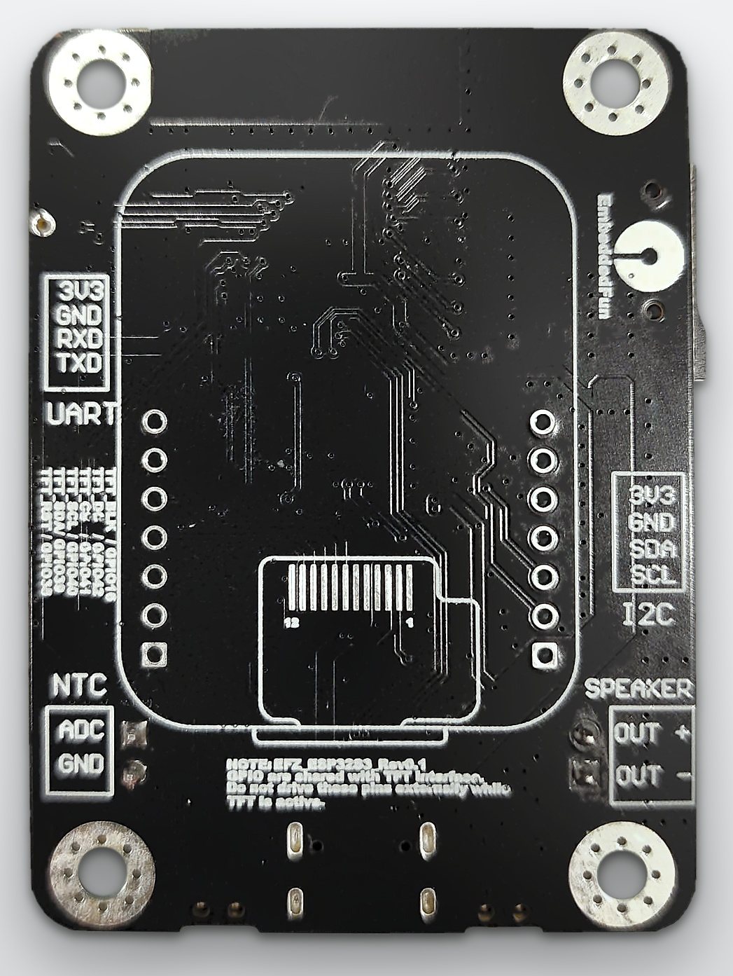
The back, display not fitted
| Function | Part | ESP32-S3 pins | Notes |
|---|---|---|---|
| USB | native USB Serial/JTAG | D− GPIO19, D+ GPIO20 | flashing + console |
| UART0 | box header P6 | TX GPIO43, RX GPIO44 | free for your own use |
| I2C (shared) | SHT30 @ 0x44 | SDA GPIO17, SCL GPIO18 | also on box header P5 |
MPU-6500 @ 0x69 | same bus, INT → GPIO48 | ||
| ADC | NTC 10 kΩ B3950 (header P7) | GPIO1 (ADC1_CH0) | 10 kΩ pull-up to 3V3 |
| RGB LED | WS2812B | GPIO21 | |
| LEDs | LED1, LED2 (red) | GPIO46, GPIO45 | active-high |
| Buttons | BOOT, RESET | GPIO0, CHIP_PU | BOOT is usable as a button |
| microSD | 4-bit SDIO | CLK 9, CMD 10, D0 8, D1 7, D2 12, D3 11, CD 6 | |
| Microphone | INMP441 (left channel) | BCLK 2, WS 4, DOUT 3, EN 5 | |
| Speaker | MAX98357A | BCLK 34, DATA 33, WS 35, SD 47 | SD low (10 kΩ pull-down) keeps the amp off |
| Buttons | BN1, BN2 | GPIO36, GPIO37 | active-low, 10 kΩ pull-up |
| TFT | SPI display connector | SCL 40, SDA 41, CS 39, DC 38, RST 42, BLK 16 | shares header P4 |
| Header P4 | 7-pin | 3V3, GPIO42, 41, 40, 39, 38, GND | |
| Header P3 | 7-pin | 3V3, GPIO26, 16, 15, 14, 13, GND | silkscreen differs — see errata |
GPIO38–42 go to both the TFT connector and header P4, and GPIO16 (backlight) is on header P3. With a display plugged in, don't use those header pins for anything else.
Strapping pins
The ESP32-S3 samples four pins at reset and latches them until power-off; after that they're ordinary GPIOs. This board uses all four, safely:
| Pin | Controls | Chip default | On this board | Result |
|---|---|---|---|---|
| GPIO0 | boot mode | weak pull-up → 1 | BOOT button + 10 kΩ pull-up | runs from flash; hold BOOT for download mode |
| GPIO46 | boot mode, ROM log | weak pull-down → 0 | LED1 + 1 kΩ to GND | 0, as download mode requires |
| GPIO45 | VDD_SPI voltage | weak pull-down → 0 | LED2 + 1 kΩ to GND | 0 → 3.3 V, which the EN25QH64A flash needs |
| GPIO3 | JTAG source | floating | INMP441 data out | ignored unless the STRAP_JTAG_SEL eFuse is burned (it isn't by default) |
GPIO45 = 1 at reset switches VDD_SPI to 1.8 V. The 3.3 V flash then can't be read and the board won't boot. If you hang anything on LED2's pin, keep it low (or high-impedance) during reset.
Source: ESP32-S3 datasheet, §3, Tables 3-1 to 3-5.
Which free pins are safe?
Besides the strapping pins, the datasheet ranks GPIOs by how freely you can use them (§2.3.5). Here's how that plays out on this board:
| Pins | Status on EFZ-ESP32S3 |
|---|---|
| GPIO13, 14, 15, 26 | free on header P3 — use these first |
| GPIO16 | free on header P3 unless a TFT is fitted (it's the backlight) |
| GPIO38–42 | on header P4, shared with the TFT. GPIO39–42 are also the chip's pad-JTAG pins; that's fine, since JTAG debugging goes over USB on this board |
| GPIO43, 44 | UART0 on box header P6. The ROM prints its boot log here too |
| GPIO15, 16 | can also take an external 32 kHz crystal (XTAL_32K) — not fitted on Rev 1 |
| GPIO26 | also SPICS1, the chip-select for an optional external PSRAM — none is fitted, so it's an ordinary GPIO here |
| GPIO27–32 | don't use — the QSPI flash bus (EN25QH64A) |
| GPIO33–37 | used by the speaker and BN1/BN2. They're only restricted on chips with octal flash/PSRAM, which this one doesn't have |
Only ADC1 (GPIO1–10) works while Wi-Fi is on; ADC2 (GPIO11–20) is shared with the radio. The NTC input is on GPIO1 (ADC1_CH0), so temperature readings and Wi-Fi coexist.
Rev 1 errata
The silkscreen next to header P3 reads 3V3, GPIO16, 15, 14, 13, 12, GND. The schematic is correct: the pins are 3V3, GPIO26, 16, 15, 14, 13, GND. GPIO12 is microSD D2 and is not on the header.
References
- ESP32-S3 datasheet
- ESP32-S3 Technical Reference Manual
- EFZ-ESP32S3 board definition in the EmbeddedFun Zephyr fork
- ESP32-S3-DevKitC in the Zephyr docs — the upstream page this one follows